Product overview:
KYN28-12 armored removable AC metal enclosed switchgear is applicable to 3.6-12kV three-phase AC 50Hz power grid for receiving and distributing electric energy and controlling, monitoring and protecting circuits. It can be used for single bus, single bus sectional system or double bus system. The switchgear shall comply with IEC298 A.C. metal-enclosed switchgear and controlgear for rated voltages above 1 kV and up to and including 52 kV;, IEC694 Common specifications for high-voltage switchgear and controlgear standards, GB3906 Alternating-current metal-enclosed switchgear and controlgear for rated voltages above 3.6kV and up to and including 40.5kV and DL/T404 Indoor AC high-voltage switchgear panel, Germany DIN VDE0670 A.c. switchgear and controlgear for voltages above 1 kV and other standards. It has perfect and reliable anti-misoperation function.
Product model description

| ① | Armored removable metal enclosed switchgear |
| ② | Movable type |
| ③ | Service conditions: (indoor) |
| ④ | Design No |
| ⑤ | Rated Voltage (kV) |
| ⑥ | Primary solution No.: |
| ⑦ | Operating mechanism feature code, D: electromagnetic T:spring |
| ⑧ | Rated Current (A) |
| ⑨ | Rated short-circuit breaking current (kA) |
Product features
KYN28-12 armored removable AC metal enclosed switchgear (hereinafter referred to as switchgear) can replace various old metal enclosed switchgear, such as KYN1-12, JYN2-12 and other series of products.Item |
Unit |
Parameter | |
| Rated Voltage | kV |
12 |
|
Rated frequency |
Hz |
50 |
|
Rated current of main bus |
A |
630,1250,1600,2000,2500,3150 |
|
| Rated Current | A |
630,1250,1600,2000,2500,3150 |
|
Rated short-time withstand current of grounding circuit(2S) |
kA |
13.9,17.4,21.8,27.4,34.8 |
|
Rated short-time withstand current of main circuit (4S) |
kA |
16,20,25,31.5,40 |
|
Rated peak withstand current (peak value) |
kA |
40,50,63,80,100 |
|
Rated short-circuit breaking current |
kA | 25,31.5,40 |
|
Rated insulation level |
1min power frequency withstand voltage |
kV |
Phase-to-phase and phase-to-ground: 42; isolating distance: 48 |
Lightning impulse withstand voltage |
kV |
Phase-to-phase and phase-to-ground: 75; isolating distance: 48 |
|
Degree of protection |
Enclosure is IP4X |
||
Structural characteristics of switch cabinet
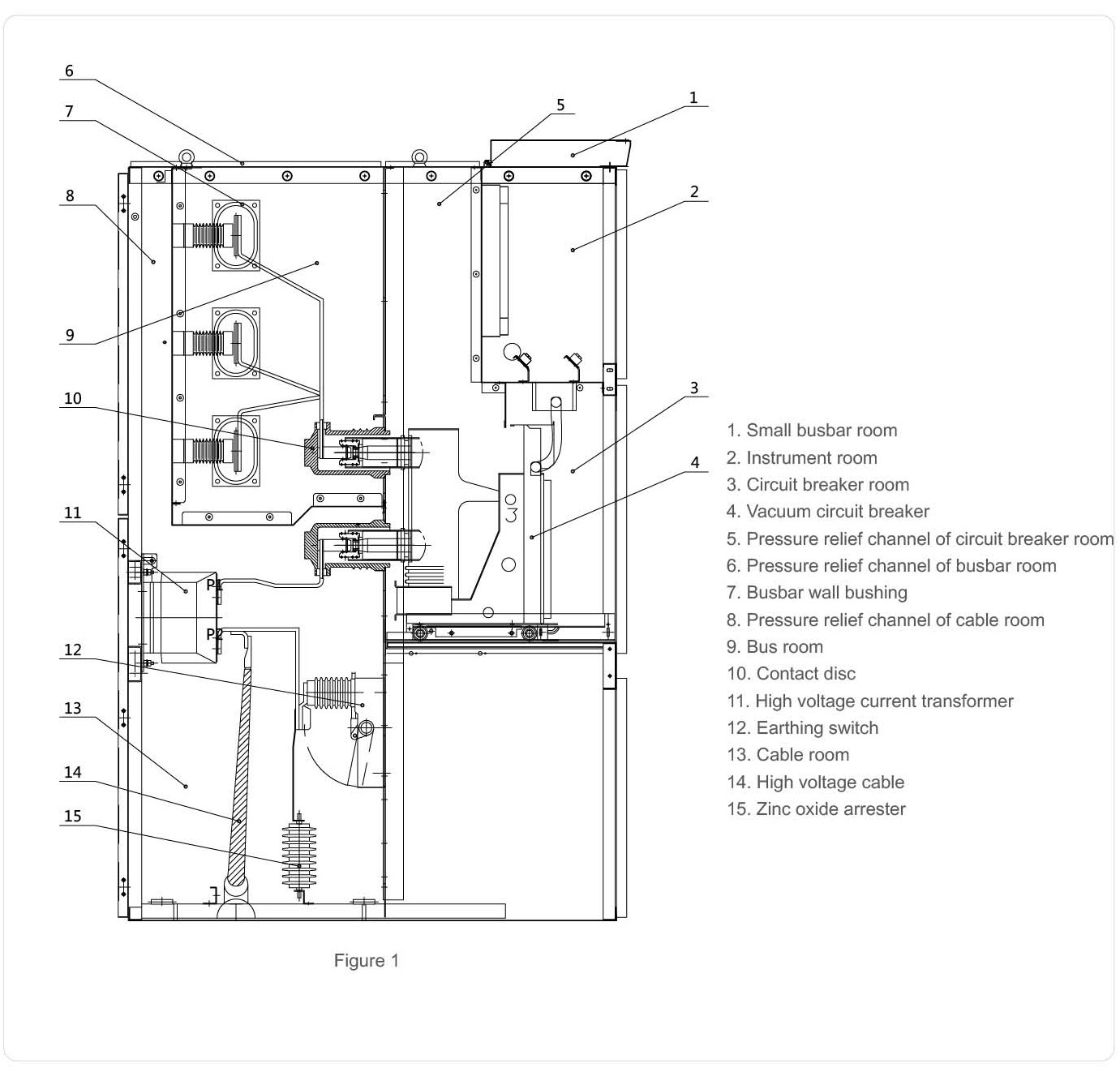
The switchgear shall be designed according to the armored metal enclosed switchgear in GB/T3906-2020. Figure 1: The switch cabinet is composed of fixed cabinet body and withdrawable parts (handcart for short). The shell of the cabinet body and the partition of each functional unit are connected by bolts. The protection grade of the switch cabinet shell is IP4X, and the protection grade when the circuit breaker chamber door is opened is IP2X. The switchgear can be equipped with vacuum circuit breaker handcart or fixed load switch. It has overhead incoming (outgoing) line, outgoing cable and other functional solutions. The switchgear can be installed in a double cabinet arrangement, that is, back-to-back or face-to-face double row arrangement.
Installation of switch cabinet
1. The switchgear shall be transported to a specific location as required by the project and indicated on the drawings. If a row of longer switchgear is arranged (such as more than 10 sets), the cabinet assembly work shall start from the middle part;
2. Use specific transportation tools such as cranes or forklifts, and do not use rollers or crowbars;
3. Draw out the circuit breaker handcart from the switch cabinet and put it in another place for safekeeping;
4. Loosen the fixing bolts in front of the bus compartment and remove the vertical partition 9;
5. Loosen the fixing bolts of the horizontal partition 19 below the circuit breaker compartment and remove the horizontal partition;
6. Loosen and remove the bottom plate 16;
7. Remove the cover plate 1 and 2 from the control trunking on the left side of the switch cabinet; Remove the right front control trunking cover plate at the same time;
8. Install the switchgear one by one on the foundation, including horizontal and vertical aspects. The unevenness of the switchgear installation shall not exceed 2mm;
9. When the switchgear is completely assembled (spliced), it can be connected to the foundation channel steel with anchor screws or welded firmly with the foundation channel steel with electric welding.
Outline dimensions of switch cabinet

Ordering Instructions
The following technical data shall be provided when ordering:
● Number of main circuit schematic diagram, purpose and main line system diagram, distribution room layout plan and arrangement diagram, etc;
● Requirements for control, measurement and protection functions of switchgear and requirements for other locking and automatic devices;
● Model, specification and quantity of main electrical components in the switchgear;
● If bus bridge connection is required between switchgear or incoming cabinet, the rated current carrying capacity of bus bridge, span of bus bridge, height from ground and other specific data shall be provided;
● When the switchgear is used in special environmental conditions, it shall be specified when ordering;
● Special requirements shall be solved through negotiation with the manufacturer.