Product model description
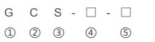
| ① |
Enclosed switchgear |
| ② |
Drawout type |
| ③ |
Electric system |
| ④ |
Main circuit solution No. |
| ⑤ |
Auxiliary circuit solution No. |
Conditions of use● Ambient temperature: no higher than+40℃, no lower than -5℃; The average temperature within 24 hours shall not be higher than +35℃; In case of exceeding, the capacity shall be reduced according to the actual situation;
● Altitude: no more than 2000m, for indoor use;
● Atmospheric conditions: the relative humidity of the surrounding air shall not exceed 50% when the maximum temperature is+40℃, and a relatively high relative humidity is allowed when the temperature is low, such as 90% when the temperature is+20℃. The influence of condensation occurring due to temperature change shall be considered;
● When the device is installed, the inclination to the vertical plane shall not exceed 50℃, and the whole set of cabinets shall be relatively flat (in accordance with GBJ232-82 standard);
● The device shall be installed in a place where there is no violent vibration and impact and it is insufficient to prevent electrical components from corrosion;
Note: When ordering this product beyond the above conditions, please consult with our company.
Performance indexThe device shall be designed in accordance with the following standards● IEC439-1 Low-voltage switchgear and controlgear assemblies;● GB 7251 Low-voltage switchgear and controlgear assemblies;● ZBK 36001 Low-voltage drawout switchgear assemblies.
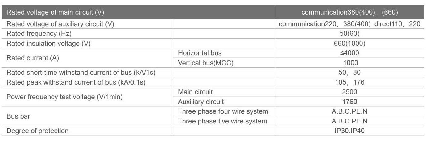
Technical parameter
Auxiliary circuit
The design of the auxiliary circuit diagram shall comply with the Technical Regulations for the Design of Auxiliary Power Supply in Fossil Fuel Power Plants and other relevant design technical regulations. It is applicable to the low-voltage power supply system in power plants and substations, and the low-voltage power distribution system in factories, mines, enterprises and high-rise buildings.
The auxiliary circuit solution is designed according to the main circuit solution, which is divided into functional units for power incoming line, feeder line (PC) and motor feeder line (MCC) operation control.
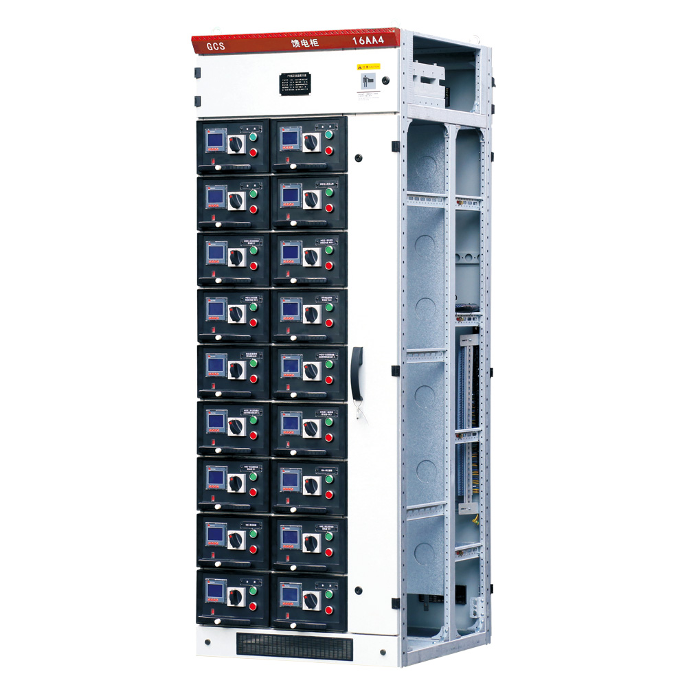
Main structure
● The main frame is made of C-shaped open section steel, with modules of 20mm, 100mm and Φ9.2mm mounting hole, with flexible and convenient internal installation;
● There are two types of main frame assembly, fully assembled structure and partially (side frame and beam) welded structure, for users to choose;
● Each functional room of the device is isolated from each other, and its compartments are divided into functional unit room, bus room and cable room; The function of each room is relatively independent;
● The horizontal main bus is arranged horizontally behind the cabinet to enhance the ability of the bus to resist electric power and make the main circuit of the device have the basic measures of high short circuit strength;
● The design of cable compartment makes it convenient for cables to enter and exit from top to bottom.
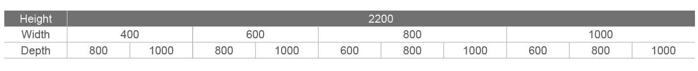
● Dimension series of general cabinet body of the device (see the table below):
Installation diagram
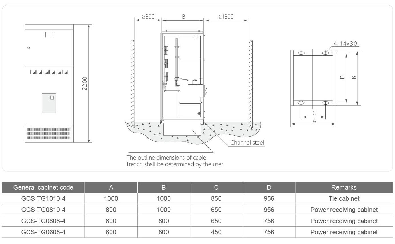
Fig. 2 Installation diagram of PC cabinet
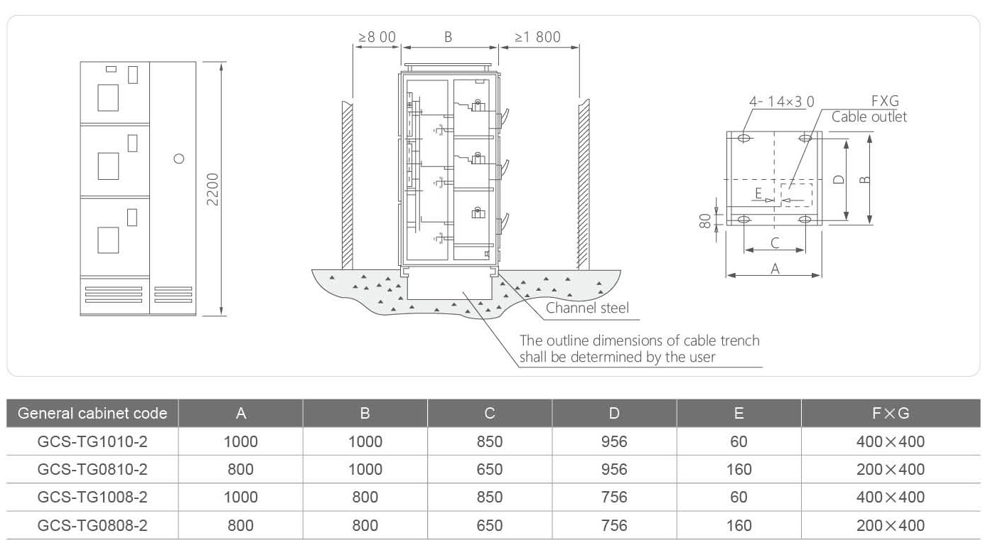
Fig. 3 Installation diagram of MCC cabinet

Ordering Instructions
The order contract includes the following contents:
● The full model of the product includes main circuit solution number and auxiliary circuit solution number;
● Combination sequence diagram of main circuit system;
● Electrical schematic diagram of auxiliary circuit;
● List of components in the cabinet;
● Voltage, current, time and other setting parameters in the circuit;
● Other special requirements inconsistent with the normal use of the product.


 WeChat QR Code
 Official QR Code